
Hydrotreating, light-ends recovery, liquid ammonia transfer and high-pressure water injection all share a difficult profile: modest flow, very high head. A conventional multistage centrifugal pump becomes tall, heavy and maintenance-intensive. High-speed pumps — integrally geared or partial-emission designs — deliver hundreds of metres of head from a single high-speed impeller, making them the compact choice for this duty.
1. How a high-speed pump works
A speed-increasing gearbox raises motor speed to well over 10,000 rpm. The impeller imparts kinetic energy to the liquid, and a diffuser or volute converts it into pressure. The main assemblies are the gearbox, high-speed shaft, inducer, impeller, diffuser, mechanical seal and a forced lubrication system. Compared with a multistage pump there are fewer parts, a shorter axial footprint and fewer maintenance points — but manufacturing accuracy, balancing and oil cleanliness become far more critical.
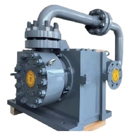
2. Where they perform best
Low flow / high head: typically a few to several tens of m³/h at heads of several hundred metres, the range where high-speed pumps clearly outperform alternatives.
Relatively clean fluids: light hydrocarbons, LPG, liquid ammonia, methanol, condensate and boiler feedwater. Solids or coking tendencies accelerate impeller and diffuser wear.
Limited NPSH: where suction conditions are tight, an inducer ahead of the impeller improves suction performance.
Compact installations: skid-mounted units, offshore platforms and revamp projects frequently favour vertical high-speed designs.
3. Critical engineering points
Cavitation control: high speed raises NPSHr, so NPSHa must be calculated carefully; consider an inducer, higher suction level or reduced fluid temperature.
Rotor dynamics: the high-speed shaft and impeller need precision balancing (commonly G2.5 or better), plus verification of critical speed, bearing stiffness and axial thrust balance.
Lubrication and sealing: the gearbox requires continuous clean forced lubrication; high rubbing speed at the seal calls for careful face material and flush plan selection per API 682.
Materials: wetted parts are selected for corrosion resistance — 316L, duplex or nickel alloys. Impellers are frequently precision cast or fully machined on 5-axis centres to keep flow passages consistent.
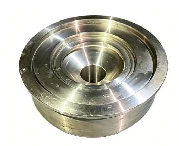
4. Typical failures and prevention
Most problems cluster around cavitation erosion, bearing and gear wear, seal leakage, and overheating caused by insufficient minimum-flow protection. Maintain oil quality and temperature, monitor vibration and bearing temperature, avoid prolonged operation below minimum continuous flow, and provide a minimum-flow bypass as required by API 610. Before restarting after a shutdown, confirm pre-warming and manual turning.
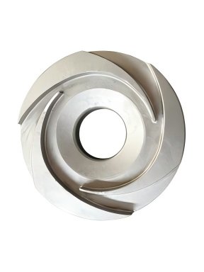
5. GiantRoc’s capability in high-speed pump components
GiantRoc manufactures precision parts for high-speed pumps: impellers, inducers, diffusers, guide vanes, high-speed shafts, bearing bushes and seal rings. With 5-axis machining centres, CNC vertical lathes, CNC floor-type boring and milling machines, welding robots and Mitsubishi wire EDM, supported by a Schenck balancing machine, Hexagon CMM and optical spectrometer, and managed through ERP/PLM/CAM systems, we apply instrument-based inspection across incoming material, in-process and final stages for full traceability.
For custom machining or reverse engineering of impellers, inducers and diffusers, please contact us through the inquiry form.
General engineering guidance only; verify all parameters against process calculations and manufacturer documentation.